The MGA With An Attitude
MGAguru.com MGAguru.com
FUEL GAUGE CALIBRATION -- FG-102b

Okay, if you're here you didn't take the shortcut, so here come the fun details. After fiddling with a handful of resistors and twisted wires for a while I decided it was too much PITA and took a quick trip to RadioShack for about $10-USD worth of trinkets. Just another half hour of tinkering yielded up the test box shown below. Before I go on here's a full list of materials purchased.

Project box, 5 x 2.5 x 2          $3.29
2-pole 6-position rotary switch	  $1.69
2pcs Plastic knob 1/4 shank       $1.29
Coaxial DC power jack 2.5mm       $1.69
10pcs 68 ohm 1/2 watt resistor    $ .98
5pcs 100 ohm 1/2 watt resistor    $ .49
               Tax       $  .64
               Total     $10.07

Mind you I didn't use quite all of these bits, but there were some additional materials scrounged from the workshop:

A few colored wires
A few crimp on wire terminals
One screw type hose clamp
One small rubber grommet
Solder
Masking tape
One 12VDC 1-amp power pack (previously $3 from surplus store).

Inside rear view of test box with details
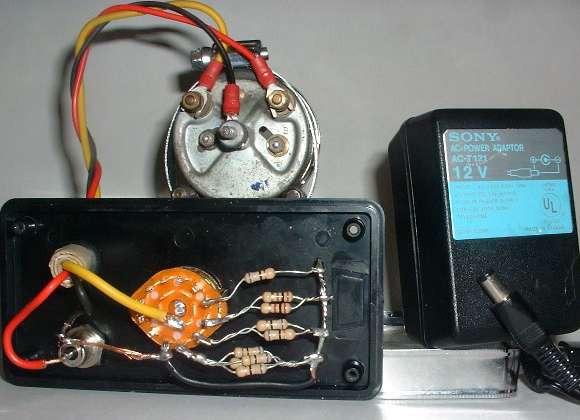
Inside rear view of test box with details.
 

The power pack was just a matter of convenience for working at my computer table where the digital camera was handy, but you can use any 12 volt DC supply with 300ma capacity (4 watts), which could just as well be your car battery. And in the end you can accomplish the necessary task using just two 68 ohm resistors and jumper wire(s). So for only $0.50 worth of resistors you're in the calibration business. That's why the shortcut was offered after I did the development work.
test box schematic
The fuel gauge is secured with the band clamp passing through a pair of slots in the top side of the box. The power jack is wired with hot (red) and ground (black) wires going to the gauge, and also a ground wire going to all of the resistors and to one terminal on the switch. And lastly one signal wire (yellow) runs from the common terminal on the switch to the "T" terminal on the gauge. Polarity of the power supply is irrelevant.

The rotary switch with the resistors is emulating the remote tank fuel level sensor with several known positions (fixed resistance). The real sender unit peaks at 70 ohms with a full tank, but 68 ohms was the closest standard resister value available. The 3% error there is negligible for our purpose of calibration. The idea now is to wire in quarter values of the 68 ohms, so I was looking for values of 68, 51, 34, 17, and 0 ohms.

68 = (1) 68 ohm resistor (shown at the top of the resistor bank).
50 = (2) 100 ohm resistors in parallel (just below the 68).
34 = (2) 68 ohm resistors in parallel (just below the 50).
17 = (4) 68 ohm resistors in parallel (just below the 34).
 0 = (1) solid jumper wire (just below the 17).

test box schematic
Lastly that 6th position on the rotary switch is an unconnected terminal which will effectively disconnect the sender unit from the gauge, similar to having a broken signal wire or no ground connection at the fuel tank. This position is labeled "OFF" on the front of the box. And yes, I know there is a much simpler way of wiring the stepping resistor switch, but I didn't have four 17 ohm resistors handy (figure at right). So lets slap the cover on the box and get on with the task at hand.

HomeBackNext
Thank you for your comments -- Send e-mail to <Barney Gaylord>
© 2000, 2005 Barney Gaylord -- Copyright and reprint information