The MGA With An Attitude
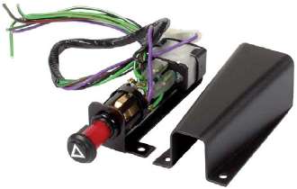
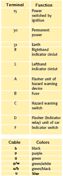
Unfortunately the diagrams do not show internal circuitry of the hazard switch. See below copy of the intructions that are packaged with the device.
Mounting & Wiring Instructions: SFB 300
The following instructions are for guidance only. If you are not sure what you are doing, refer to an auto electrician. A short circuit can cause a fire, injury or both. Mounting The device MUST be mounted where the warning light can be clearly seen by the driver. The device can be mounted under the dashboard or on the steering column. OR If the dashboard is no thicker than 1.5mm (ie a metal dashboard) it can be mounted directly to it by drilling a 15 mm hole and discarding the bracket assembly. The flasher unit should be mounted adjacent to the switch using the spring clip. If possible, mount the device so that the wires from it can reach the wires to which they need to be connected. If this is not possible, lengthen the wires by using connectors, such as insulated male and female Lucar connectors. Do not twist and tape up the ends. Wiring 1. Connect the PURPLE wire to a suitable, unswitched point or directly from the battery. 2. Cut the wire that goes from the ignition switch to the live terminal (usually marked B) on the existing flasher unit. This terminal is live only when the ignition key is ON. 3. Connect the GREEN/PURPLE wire to the wire you have just cut, coming from the ignition switch and the other GREEN/YELLOW wire to the cut end going to the flasher unit. Use the Lucar connections and make sure these are well insulated. 4. Connect the GREEN/WHITE wire that goes from the direction indicator switch to the RIGHT HAND flasher lamp circuit, using a snap lock automotive cable connector. 5. Connect the GREEN wire that goes from the direction indicator switch to the LEFT HAND flasher lamps circuit, using a snap lock (self-stripping wire connector) automotive cable connector. 6. The GREEN/WHITE and GREEN wires are interchangeable and it is not important which circuit, left or right each is connected to. 7. The BLACK wire should be connected to ground (carbody/earth). The Hazard Warning Unit has two unused terminals. These are for a vehicle which is fitted with a trailer socket and should be connected to the number 5 terminal and number 6 terminal on the socket. However a qualified electrician should be consulted for these connections as some other wires on the trailer may have to be reconnected. The part number seems to be SFB300 or alternative GSS 159 and is a reproduction of a Lucas product - although some of the boxes have Lucas on them. It's sold quite widely by Moss, Holden, Little British Car Co and others. Auto Electrical Spares say that it's made in China so I couldn't speak with the manufacturer. Some claim -ve earth only but Holden say it's for both -ve and +ve! |