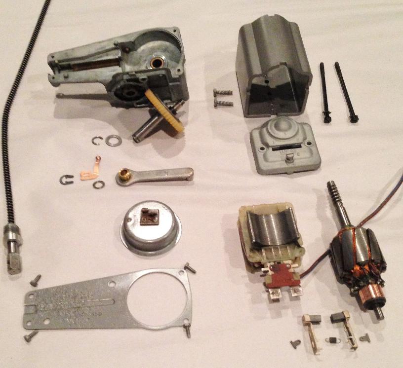
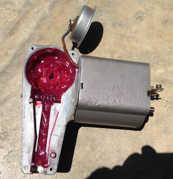
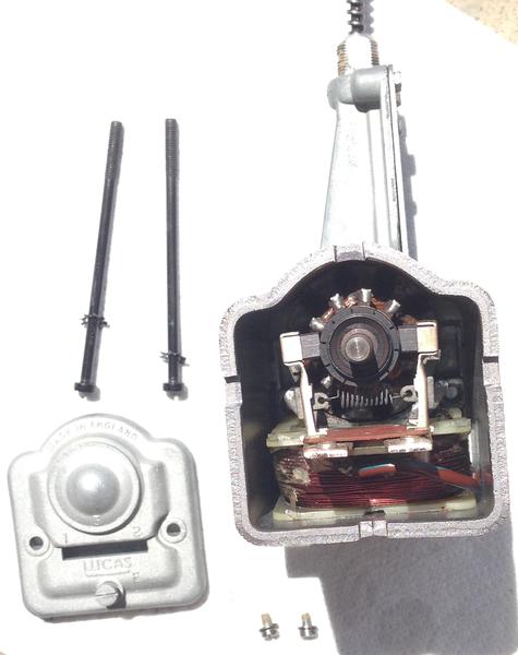
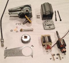
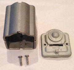
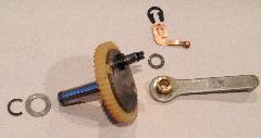
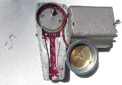
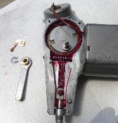
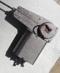
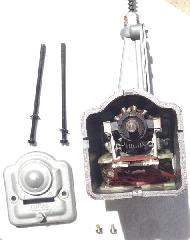
The first few pictures are just showing the various parts prior to assembly. One shot is of all of the parts laid out and the others are pictures of individual parts or sets of parts. The first picture note refers to the picture of the bottom of the motor housing with the two screws shown holding the cradle in place. The rest of the notes should be correct for the pictures in order as shown.
|
|
|
|

|
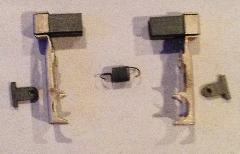
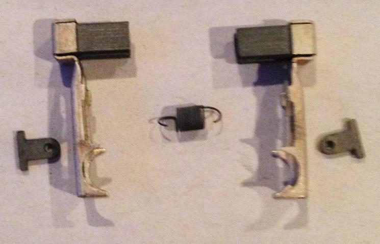
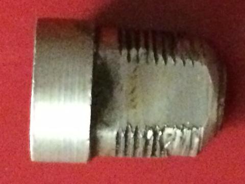
The new carbon brushes, 1/4-inch square, are too long and need to be ground shorter.
|
|
|
|
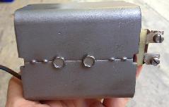
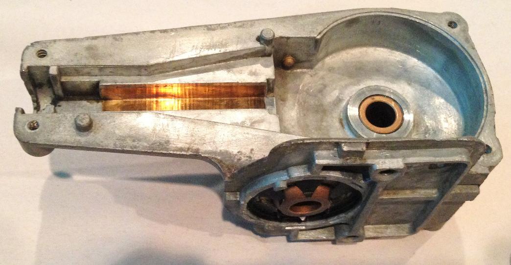
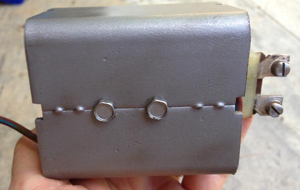
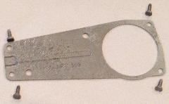
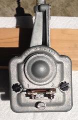
Bottom of the motor housing with the coil cradle reinstalled. Note that the two holes are closer to one end than the other so you need to install the cradle with the correct orientation. |
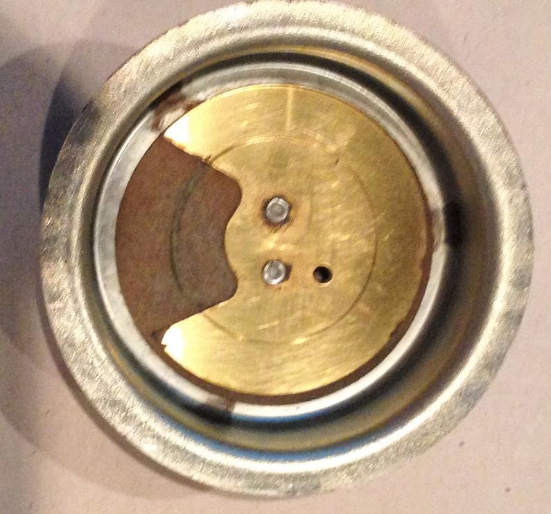
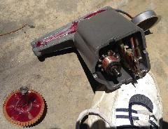
The wire going through the hole in the gear box housing and connected to the parking commutator cover (sorry about the brown with blue stripe but it was the closest I could find to a brown wire the right gauge). Note and avoid my mistake. I had to disconnect the wire from the commutator cover in order to get the cover that holds it in place onto the gear box. |
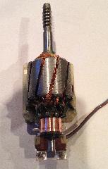
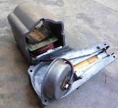
The armature reinstalled. Note that it needs to be installed from the end that rests against the gear box housing so you will need to separate them in order to get this in place. |

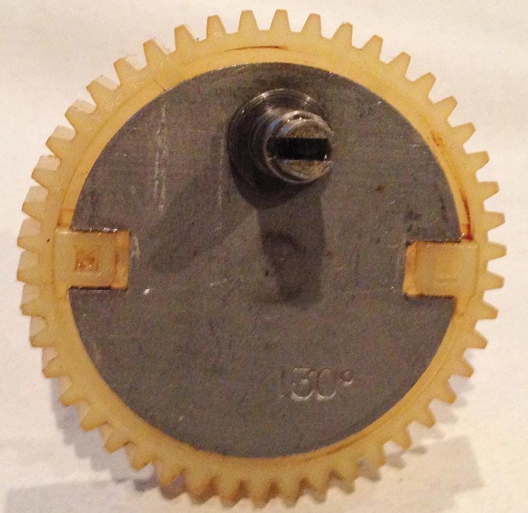
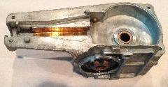
The gear box with new grease prior to replacing the crank gear. |
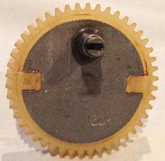
The crank gear in place with the washer and circlip that go on the bottom of the shaft to hold the crank gear in place. |
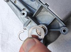
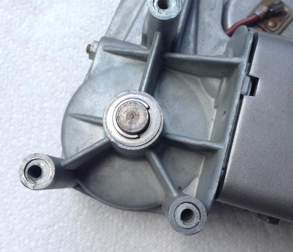
The bottom of the assembly where the crank gear shaft protrudes through. Here I am holding the washer that goes on before the circlip. |
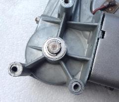
The washer and circlip in place holding the crank gear in place. |
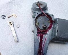
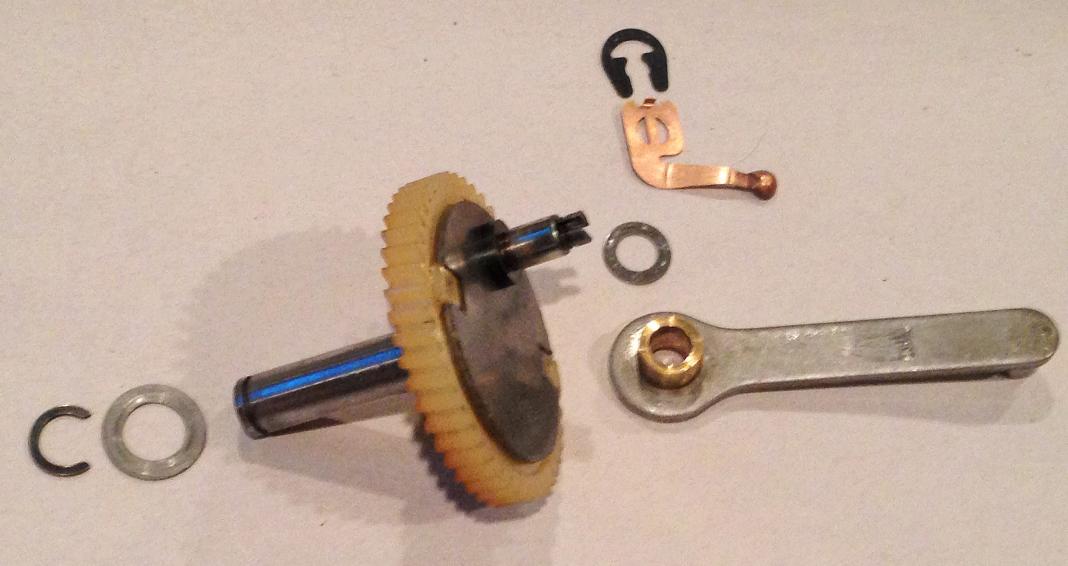
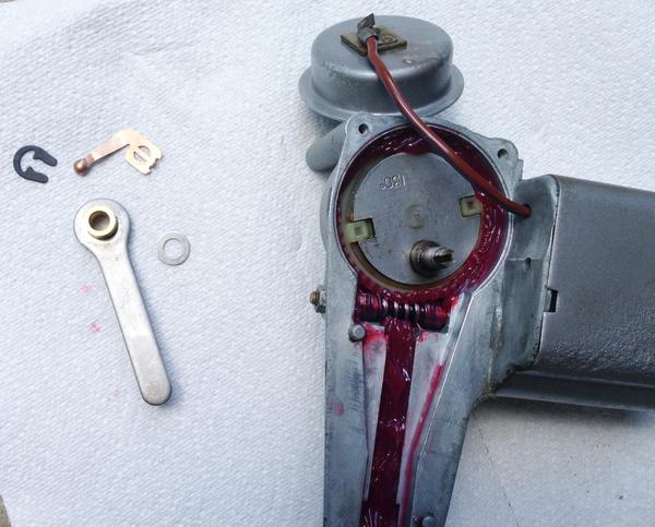
The assembly turned back over with the washer, crank link, parking commutator contact and circlip off to the side. |
The washer placed onto the shaft on the crank gear. Note that this needs to go on first. |
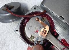
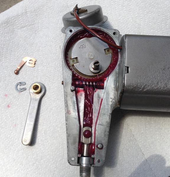
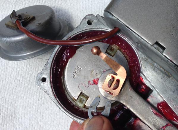
The crank link and the copper parking commutator contact in place with me holding the circlip ready for installation. Note I have also installed the cable which is shown in the next picture. |
The washer, crank link, parking commutator contact, circlip and cable installed. I think this is the point that I realized that I had to disconnect the wire from the parking commutator cover. As youll see in the next picture, I have fixed that mistake. |
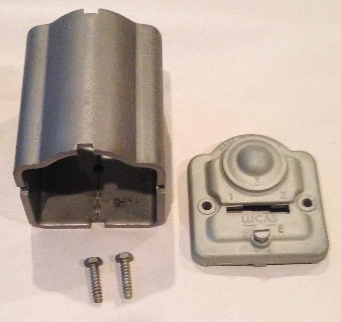
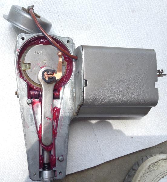
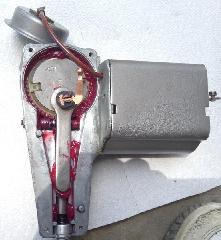
The gear box cover and the parking commutator cover in place with the four screws that hold the cover in place off to the side. |
The gear box cover attached. |
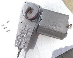
The new brushes installed. Note that I scavenged them from a non-working orbital sander that I had laying around. They were too long so I sanded them down to fit. The motor cover and long screws that hold the motor housing to the gear box are off to the side. |
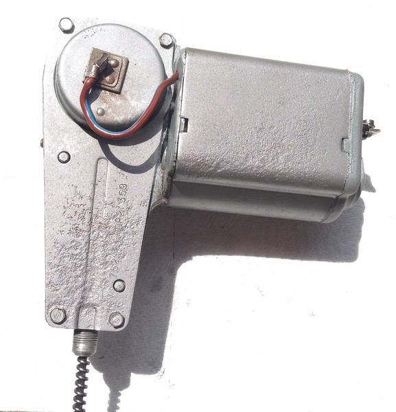
The unit with the motor cover attached. |
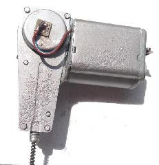
The complete unit reassembled and ready to go.
 |
 |