The MGA With An Attitude
INSTALLING AFTERMARKET HORNS - ET-208

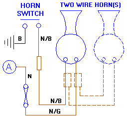
Check this diagram first to remind yourself of the original horn wiring. You will notice that power is supplied to the horn from the fuse which is always hot (not switched), so the horn will work even when the key is switched off. The circuit is completed by making a ground connection with the horn button in the dash. As such, the entire circuit inside of the original horn has to be isolated from the case so it is not grounded on the chassis of the car.
Some aftermarket horns have only one wire. These are normally expected to be grounded on the chassis, in which case the power wire wants to be switched by the horn button. One way to do this is by routing the fused power to the wire on the button which is normally connected to ground at the fuel gauge bracket. That requires either ripping the original brown/green wire out of the harness for re-routing, or the installation of a new wire. The other side of the switch is a little hokey as well, as you end up with switched power on the brown/black wire in the harness (the normal color code for a switched ground wire) which could cause confusion for future maintenance. You would also have to ground the horn(s) on the chassis of the car. It is not desirable to tear into the heart of the wiring harness for such major wire re-routing just to install a new horn.
A second and more common solution is to electrically isolate the aftermarket horn from the chassis. Many single wire aftermarket horns are supplied with an electrically isolated mounting bracket (plastic or rubber bushings around the screws) for exactly this reason. Then attach a ground wire to the case of the horn which will be routed back to the horn button for switched grounding. When you do this, touching a metal wrench between the horn case and the chassis will make the ground connection and make the horn sound. That is not usually a problem in every day operation, and it won't blow the fuse, but it could give you a surprise if you're working in that area. If the horn is mounted too close to some grounded part of the car chassis, then bumps and vibration down the road could cause the horn to make contact with ground and sound intermittently while driving. So just be careful not to put the new horn too close to the chassis.

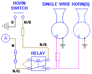
A third solution is to install a simple 3 or 4 terminal relay near the horn. Connect the original power wire to one terminal of the relay trigger coil. Connect the original horn button wire to the other terminal of the relay coil. Then pressing the horn button makes the ground connection to activate the relay. Also connect the original power wire to one power terminal of the relay, and connect the other power terminal of the relay to the horn. This will supply power to the horn when the relay is activated. Then the horn needs to be grounded on the chassis to complete the circuit for the horn. This does not require any changes to the original wiring harness. The original brown/green wire in the harness still carries power to the horn, but the original brown/black wire in the harness is then only switching the relay signal current. Eliminating the electrical resistance of the small return wire in the power circuit may actually result in slightly improved voltage and power to the horn. That could be significant if the new horn draws more power than the original horn.
|

