The MGA With An Attitude
At 09:00 PM 9/9/03 -0400, Steve Demko wrote:
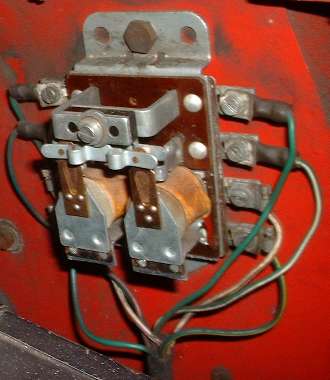
For testing and debugging the brake lights and turn signals you need the ignition switch turned on. If you leave the ignition on for more than a few minutes at a time without the engine running, you run a risk of burning out the ignition coil. So before you go into this routine, disconnect one primary wire from the ignition coil, either the hot white or the white/black going to the distributor. The first thing you should notice in the wiring diagram is that the turn signals and brake lights are sharing the ground connections with the parking lights and tail lights. So be sure the tail lights work (prior course) before going here. You should also notice that the brake lights and rear turn signals on the MGA 1500 share the same high intensity filament in the single bulb in the rear lamps. This is what makes the big turn signal relay box necessary. When you switch on a turn signal, the relay disconnects the rear lamp from the brake light circuit and connects it to the front lamp and to the flasher unit with a 3-way relay connection. So before you go into the turn signals, you want to test the brake lights. When the tail lights work (checking first for good ground), then switch on the key and step on the brake pedal to see if the brake lights work. If you get no brake lights, then check for power at the brake light switch. This is on top of the frame below the starter switch. The green wire should be hot with the switch on. If not, then back up one connector in the harness and look for power at the bullet connector in the engine bay, a 2-green-wire connector near the starter switch. Go no farther until you have power at the brake light switch. With power at the brake light switch, step on the pedal again. If you still have no brake lights you may have a bad hydraulic switch. Connect a jumper wire across the brake light switch to bypass it. If the brake lights work, then you need to replace the switch. If the brake lights still don't work, then leave the power jumper connected across the switch and move on to the next connector in the harness. Find the 2-wire green/purple bullet connector near the starter switch. Check for power there which will now be coming from the brake light switch jumper. Clean the contacts if necessary to assure good connections at this location. Check again to see if you have brake lights. If still no brake lights, then go to the next junction for that circuit, the green/purple wire on terminal 5 of the turn signal relay. Check for power at this terminal. If no power here, back up one paragraph, because you missed something. If you should ever find power at one end of a wire and no power at the other end of the same wire, the you have a broken wire (which is virtually impossible unless the harness is burned). Once you have power on terminal 5 of the relay, the brake lights should be lit. If not, immediately check for power on terminals 3 and 7. If power on 5 but not on BOTH 3 and 7, then you have a bad normally closed contact in the relay. Then you may get your first look inside the relay. Or you may have to do this later for other reasons anyway. With the cover removed from the relay you can use emery paper to clean the contacts, as with any typical relay contacts.
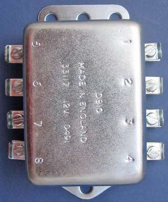
In a separate important paragraph here I want to remind you that there are really NINE electrical connections to the turn signal relay. Take another look at the schematic. The relay has an internal ground connection for the operating coils, so the case of the relay has to be grounded on the body of the car for the relay coils to work. If the car was recently painted, or if you have recently had the relay dismounted from the bulkhead, you may not have a good ground connection. Use a battery powered test lamp or an ohm meter to check for ground continuity between the relay case and chassis ground. Otherwise use a jumper wire to apply power to terminals 4 and/or 8, and if the relay clicks it does have a good ground connection. If the relay case is not grounded, you can use internal tooth lockwashers to cut through the paint where you install the mounting nuts on the back side of the bulkhead, or just scrape off a little paint so one of the screws can get a ground connection there. Back side of the bulkhead is not an appearance problem, and it's in a protected environment to minimize corrosion. If perchance the relay grounding doesn't make it click with power on 4 or 8, then you need to find and restore the ground connection for the coils inside the relay (hardly ever a problem). When you connect case ground and a power wire to either terminal 4 or 8, one of the relays should click, even if nothing else was connected. Getting back to the real problem, you must have internal power connections from terminal 5 to terminals 3 and 7. Then with power on 3 and 7 the brake lights should be lit. If not, then follow the diagram to check the next connectors in the harness, the white/purple and white/brown bullet connectors near the starter switch. Having verified those connections, move on to the white/purple and white/brown bullet connectors in the harness behind the right rear tire. Having verified good power there, move on to the tail lamp fixtures to verify power on the white/purple wire at left side lamp and white/brown wire at right side lamp. With both power and ground at the fixtures, if you still don't have brake lights you have burned out bulbs or bad connections on the base of the bulb. Check for free motion and spring force of the contacts in the bulb socket. Clean contacts with CLR and a Q-tip. Do whatever you need to get the brake lights working before going on to the turn signals. Now the next funny problem that is actually fairly common. Switch on parking lights and verify that the tail lamps are working. Switch on ignition and step on brake pedal to actuate the brake lights. If a tail light goes out when you apply the brakes, that is indication of a bad or broken ground connection on the lamp fixture. What happens is that the tail light finds a ground path through the brake light filament, then through the turn signal relay contact (on the 1500 car), and then through the opposite side brake light filament to a good ground wire. Because the brake lamp is higher wattage than the tail lamp, the resistance in the brake lamp filaments is much lower than the resistance in the tail light filament. As a result, the tail light can light up using the moderate resistance ground path through the brake lamps, but the tail lamp will be not so bright as if it had a good direct ground connection. So when you hit the brakes the tail light goes from dim to dark rather than the brake light going from dark to bright. In this case, fix the ground connection for the offending lamp, and be sure the brake lights work properly before going on to the turn signals. "In checking the direction indicator relay I get a good reading at the number 1 terminal which has the green/brown wire attached to it but no readings at any of the other 7 terminals on the relay switch." Referring to "circ_f2.htm", at rest with ignition on, terminal 1 is the only terminal that should have power. All is well at that point. The power comes from the flasher unit, which has a few interesting characteristics. The open circuit voltage here is full system voltage of 12 volts only because the output is not connected to anything. The flasher unit has some internal resistance when at rest, so connecting any electrical load to this terminal will induce a voltage drop through the flasher unit. Even connecting a small test lamp will drop it by 2 or 3 volts. For the curious, I have in another article a full dissertation on how the flasher unit works (which you may have already read). ".... Do you think the problem is in the direction indicator relay switch or something else like a short." I dunno, yet. The relay could go bad in a number of ways, but it's more likely something wrong with your harness connectors or lamp fixtures. "Is there a way to check the function of the directional indicator relay? ...." Yep. There sure is, and pretty easy too. You just need a jumper wire with alligator clips, and a test light. Keep looking at "circ_f2.htm". Connect a jumper wire to power at the fuse box. Touch hot wire to relay terminal 2, and the RF turn signal lamp should light up. Touch hot wire to relay terminal 6, and the LF turn signal lamp should light up. Touch hot wire to relay terminal 3 or 7, and the brake lamps should light up, both sides, because they're connected together inside the relay. If that works so far, you have just verified all of the circuitry for all four turn signal bulbs. In fact you must be able to light up all four bulbs in this manner before testing the relay. If any one of the four corner bulbs does not light, go back and fix that problem first. Diagnosis and repair here is similar to any lamp. Check and verify good ground connection at the lamp first (which you should have already done in the prior Lighting Gremlins course). Then follow the power one connector at a time beginning at the source. By prior instruction here you should already have the brake lights working. For the front turn signal lamps the power runs on one continuous wire from the relay to a snap connector less than a foot from the lamp. When you have verified that all wiring and lamps are working as they should, then you can test the flasher and the relay. Connect the jumper wire from terminal 1 to terminal 3 or 7. From the circuit diagram you can see this will be connecting the two rear brake lamps to the flasher unit by way of the normally closed contacts inside the relay. In this case the flasher unit should cycle in a normal manner while the brake lights flash. This will verify proper operation of the flasher unit even if other parts of the relay do not work. Cute, huh? If both brake lights light up properly by touching a hot wire to either terminal 3 or 7, but the flasher unit doesn't make them flash, then the flasher unit is faulty and needs to be replaced (or maybe it's miswired). If the flasher unit is not working properly, then bypass power by installing a jumper wire from "B" to "L" on the flasher, or from a hot terminal on the fuse box to terminal 1 on the turn signal relay. You can still test the rest of the functions of the relay, but it's more convenient to verify things if the flasher unit is working properly. Now connect a power jumper wire from the fuse block to relay terminal 4, go ahead and clip it on. You should hear a loud CLICK from the relay, followed by a short pause of about 1/2 second, followed by a second click from the flasher unit making the right side turn signals light up (front and rear). This should be followed by regular clicking from the flasher unit as the right turn signal flashes. The indicator lamp on the dash should also be flashing in unison with the turn signal. All this time the relay is being held in a static closed condition (after the very first click), and the flasher unit is doing all the work. When you disconnect the hot wire from terminal 4, the relay will drop out with another loud click, and the flashing will stop. When you connect the hot jumper wire to relay terminal 8, all the same things should happen, but this time the left side turn signals should be flashing. Now you have three ways to make lights flash, left side, right side, or rear lights. There is a simple bit of binary logic that can apply here if one or two of these things does note work. If the right side flashes, and the left side does not, then the failing lamp is on the left side. If the left side flashes, and the right side does not, then the failing lamp is on the right side. If the rear lamps do not flash, the failing lamp is in the rear. If the rear lamps do flash, the failing lamp is in the front. In this manner you can quickly detect which corner has the bad circuit. As to testing the relay itself, it only does two things. When you connect power to terminal 4 it switches the right directional relay. When you connect power to terminal 8 it switches the left directional relay. If you have verified all of the lighting circuits and the flasher as working first, then any failure of the turn signals will be because of a fault in the relay. If it clicks once for both directions, then the relays are physically operating, and you must have some bad contact on the relays. That's easy to check (when you have the cover off). Operate the relay in question with a power jumper. Observe the relay armature and contacts operating. Press one finger gently on the contact blade to see if that will make the connections work. If it does, then simply cleaning the contacts might cure all ills. Otherwise you may need to do a little creative armature bending to realign the working parts of the relay so that it will connect with two contacts at the same time when it operates. Considering that this fancy turn signal relay is just two simple relays under one cover, and it may cost a small fortune to replace, it can pay nicely to fix whatever is ailing it rather than buying a new one. That's when you can get back to having obscene amounts of fun with your LBC without spending obscene amounts of money doing it (the very purpose of my web site). Additional comment: The MGA 1500 circuitry has the turn signals sharing the rear bulbs with the brake lights, so if the turn signals are not working you may also not have a brake light on that side of the car. While the signal is switched on the rear bulb is disconnected from the brake light circuit, so it would just go dark and remain dark (as long as the turn signal is switched on but not working). Switching off the turn signal could restore operation of the brake lamp, if the fault is in the front lamp circuit. This malady only affects the MGA 1500. The MGA 1600 and all MGB have separate rear lamps for brake lights and turn signals and do not use this turn signal relay. This quirk of the MGA 1500 turn signals has a couple more strange implications. If the right signal fails, only the left brake lamp lights up with the brake applied. If that isn't bad enough, pumping the brake pedal will flash the left brake, which is not the signal you had in mind when turning right. But if the fault is in the right front lamp, and the right rear lamp works, then holding the brake pedal down while manually switching the turn signal dash switch on and off for a right turn signal will flash the right brake light. From behind this would look exactly the same as a working right turn signal (for as long as you're holding the brake pedal down). When you have figured out why this works, and can do it on a moment's notice if a turn signal should fail unexpectedly, then you would be an ace MGA/Lucas electrical technician. |