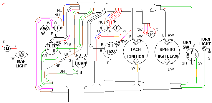
 There is a small trick to the wiring harness for the MGA. Apparently it was originally designed for a right hand drive vehicle, and then the design was "adjusted" slightly to allow for installation of the same harness in a left hand drive vehicle. The first illustration above shows the dash harness layout for RHD installation, looking at the face of the dash. Notice that the tachometer is to the left of the speedometer, and the safety gauge (oil pressure and water temperature) is to the right of the fuel gauge. This puts the safety gauge next to the tachometer where it is most convenient to see both at a glance.
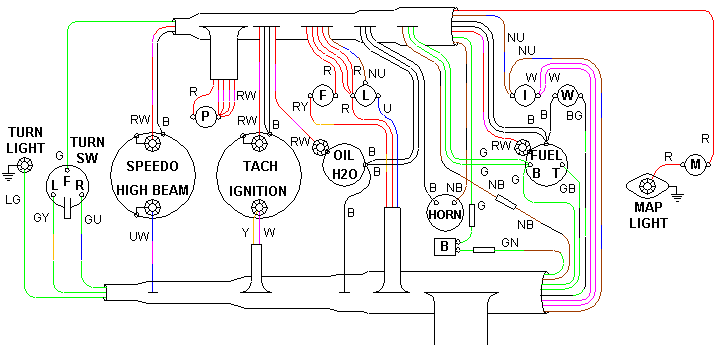
The second illustration above is essentially a mirror image of the first. This is appropriate for the rear view of the RHD installation. It is also appropriate as the face view of the LDH dash if you install the tachometer next to the safety gauge (which is non-standard). From the factory all MGA originally had the tachometer to the left of the speedometer, and the safety gauge to the right of the fuel gauge. For the LHD cars this puts the tachometer and safety gauge very far apart, which always seemed strange to me. It also requires that some of the wires will be longer than you might think necessary, so they can reach the alternate instrument positions using the same harness. It is a common modification for LHD cars to put the tachometer to the right of the speedometer and the safety gauge to the left of the fuel gauge, so the tachometer and safety gauge will be close together for easy viewing.
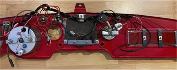
The harness is not drawn to scale, but the relative position of the wires as they break out of the cables is correct. This makes for easy hookup and minimal crossover of the wires. The small dash sub-harness is shown above the instruments, and the larger main harness is shown below the instruments. This is designed to allow installation of the dash harness as part of the dash assembly before the dash assembly is installed in the vehicle. The main harness is intended to be placed in the vehicle first, then the dash assembly is to be "offered up" near its installation point, and the main harness wires connected just before the dash is secured in place. All of the sockets for illumination and indicator lamps are originally pre-wired as part of the harness and will plug into the appropriate positions (without tools). There is only one wire in the (upper) dash harness which does not connect to a dash mounted device. The Brown wire with Black stripe (NB) has bullet connectors on both cables and will be connected with a female connector at final installation.
Wires for the ventilation blower switch (which was part of an optional accessory) also use bullet connectors. When there is no blower switch installed the bullet connectors on the harness should be covered with female connectors to protect them from shorting out on anything.
The map light and turn indicator warning light need to be grounded on the dash, and the dash in turn grounded on the car body. Be sure to scrape off a little paint or otherwise install an additional grounding wire for these lamps. The instruments are all intended to have Black grounding wires from the harness attached to the mounting brackets. The only instrument which requires an electrical ground for operation is the fuel gauge. Otherwise the instrument grounding is done to service the lamps. There is just one Black ground wire in the main harness at this point. All the rest of the Black wires are daisy chained together in the dash harness. The Black wires all terminate with ring terminals, except for the one connecting to the wiper switch. All other wires are originally stripped with bare ends for connection to screw post connectors.
Some modern replacement switches, especially the ignition switch, may be supplied with Lucar push-on spade connectors. In this case you would need to install female Lucar connectors on the matching wires (which originally have bare wire ends).
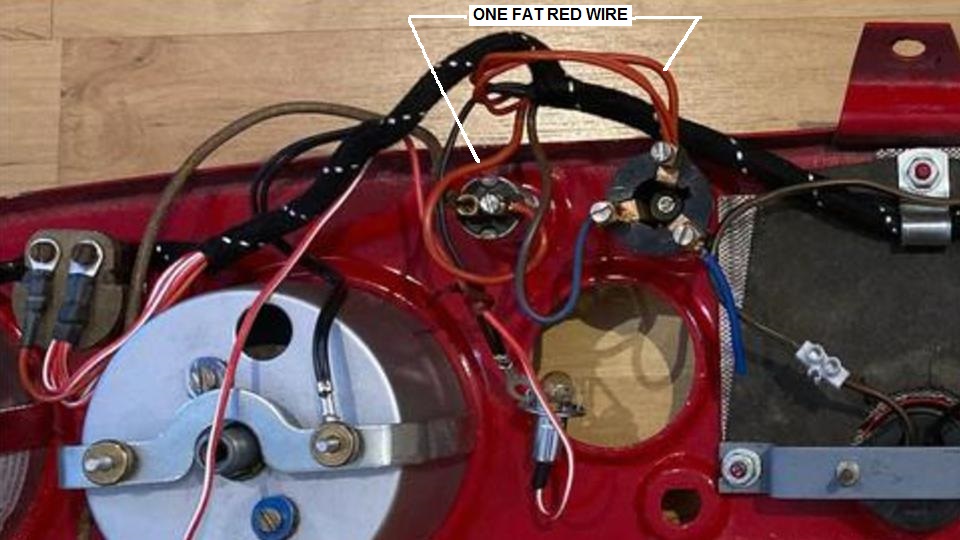
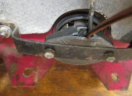
There is a small "gotcha" to watch out for. The lighting switch is directly adjacent to the fog lamp switch on the
 dash panel. The red wire connecting lighting switch S1 terminal to the fog lamp switch may have both ends extending from the same location on the wiring harness (along with other red wires which connect to the lighting switch). One of those common red wire ends needs to be connected to the fog lamp switch. If you get this wrong the (optional) fog light(s) will not work, and also either the map light or the dash illumination lights or the parking and tail lights will not work. The factory tried to be helpful here, making this one Red wire one gauge thicker than the others. So connect one thick Red wire end to the lighting switch, and one thick Red wire end to the Fog switch. Truth of this is that the one Red wire is thicker because it carries higher current for the Fog or Driving lamp(s).
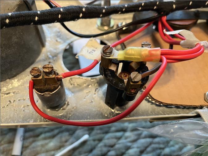
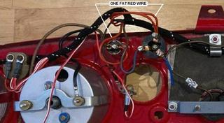
 Here is another idea on how to connect four red wires to one screw terminal on the lighting switch (and also on the dash lamp dimmer switch). Put four wires into one ring lug terminal, then connect that terminal to the switch with a screw. In this case the original set screw was a bit too long, so there is a flat washer under the screw head.
One more minor note. On close examination you may notice that the wire which triggers the left turn signal is connected to the "R" terminal on the switch, and the wire which triggers the right turn signal is connected to the "L" terminal on the switch. This is correct for the MGA. It is a function of the orientation of the operating handle on the switch.
|