The MGA With An Attitude
ALTERNATOR INSTALLATION, AC Delco - AC-202
This article with pictures was supplied by Glen Jarboe
 MGA Generator to AC Delco Alternator Conversion
Before starting my alternator conversion, I studied the write ups by
Barney Gaylord (http://www.mgaguru.com/mgtech/electric/ac201.htm) and
Teglerizer (http://www.teglerizer.com/alternator/index.html). I found both of these documents to be informative and highly instructive.
A quick reminder here that the vehicle electrical system needs to be converted from positive to negative ground.
I decided to use an AC Delco alternator for my conversion. It is a 63 amp alternator that has been used (I suspect) on tens of millions of vehicles. Its most attractive feature is that it is cheap ($25 plus a $6 core charge). At OReillys Auto, I specified a 78 Chevy Camaro, 5 liter and was surprised to find they had this old rebuilt alternator in stock. It takes a bit of effort to fit this unit into the MGA. The alternator has a wide mounting flange at the top and a small threaded one (for the adjusting bolt) at the bottom. Some have inverted the alternator and used the adjustment hole for the upper attachment point. This creates a few minor problems with size of the two holes.
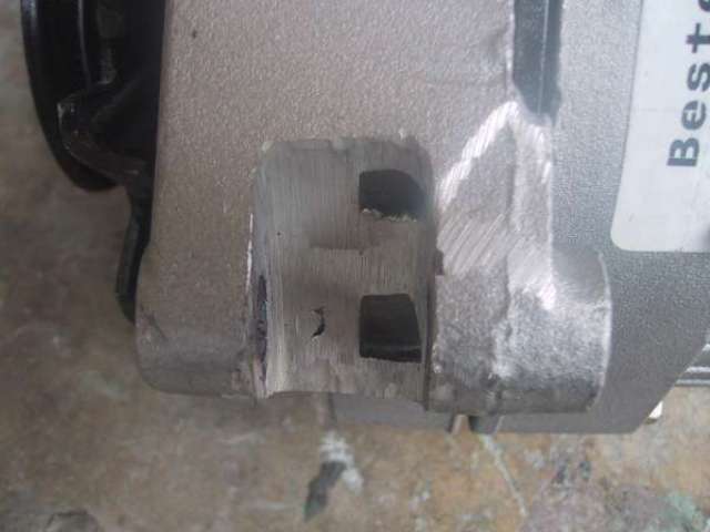
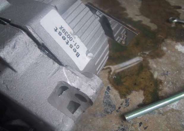
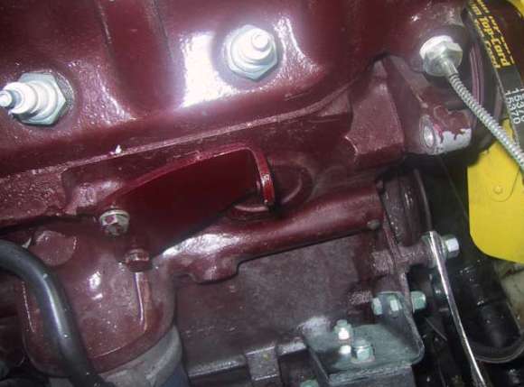
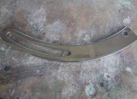
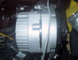
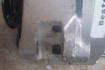 Because most of the weight of the alternator is biased toward its front, I decided to use the wide flange for my upper attachment. To fit it to the water pump mounting ear, I ground out a slot in the upper flange. This took about 10 minutes with my angle grinder. The slot is .5 inches aft of the face of the alternator and .7 inches wide. This allows the alternator pulley to line up just right with the fan pulley and the damper. I was careful not to cut the slot too wide because I wanted the through bolt to clamp the new double flange around the ear that extends from the water pump. If the slot were too wide, shims would be in order. I started out with the slot a little too narrow, progressively widening it and test fitting it around the water pump ear. Here are some pics of the slot in the alternator:
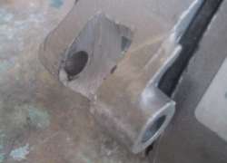
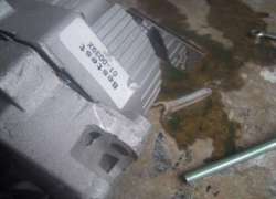
Because the wide flange has a 3/8 hole, I had to enlarge the hole in the water pump bracket to 3/8. Hanging the alternator in this fashion gave me a very sturdy upper attachment point and allowed me to use the (lower) threaded flange as it was intended. Strangely, although there is an attachment bolt hole in the back of the alternator that is 5/16-24, the threads for the adjustment bolt are 8 mm-1.25 pitch. Likewise, I think the power output nut is also metric. I used a 10 mm wrench to tighten it.
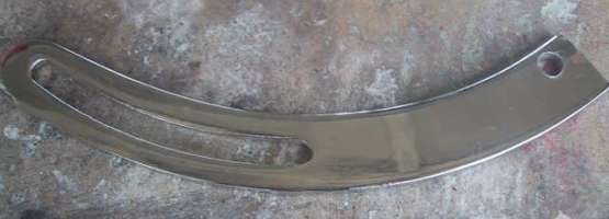
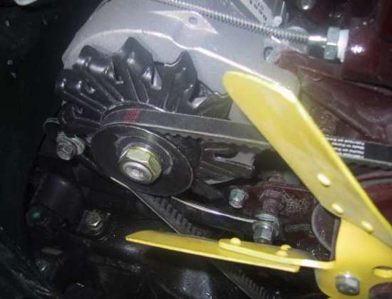
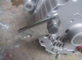
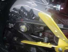
I used a J-Bracket (Mr. Gasket Part # 9851 about $ 11) for my lower adjustment arm. I cut it to a length of 8 and drilled a 3/8 hole near the end. This hole is drilled slightly off center in order to give the bracket as much room as possible to clear the fan on the front of the alternator. I did not have to do any bending of the bracket. It just clears the fan near the adjusting bolt by a few millimeters.
In order to support the alternator at the back, I used the alternator mounting bracket from an MG midget (about $ 10 used). I also used the threaded mounting hole on the back of the alternator to hold a small bracket that I created from the remaining end of the J-bracket. I drilled two 5/16 holes in this short piece of plate so that the hole in the ear lined up with the front mount. As it turned out, this added ear slipped in right behind the ear of the Midget mounting bracket without using shims or spacers.
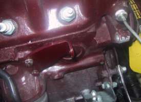
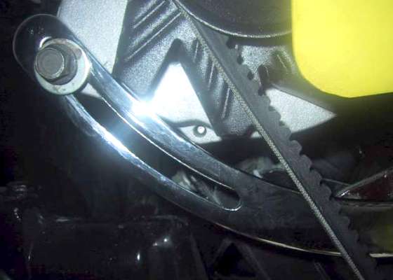
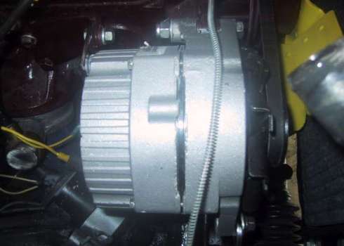
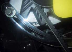
The alternator was easily mounted with a 2.5 inch 3/8 bolt and Nyloc at the front, and a 5/16 bolt at the back. The J-bracket was attached to the mounting point with the 8mm bolt. I used a 37 V-belt which gave me a snug fit with about 1 inch of remaining adjustment. Here are a few shots of the final installation which feels quite rigid to me once everything is tightened down:
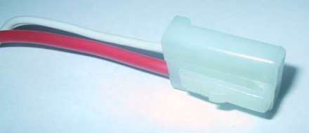
I followed Barney Gaylords write-up to make my electrical connections. A pigtail designed for this alternator was easily obtained (Caltemp Part #08602 about $3). This is nice since the wires are fully insulated up into the alternator body.
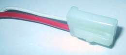 It has two leads that match up to the two lugs in the body of the alternator. These two terminals are clearly labeled on the alternator as R (Pin1) and F (Pin 2). I found a couple of sites on the internet that convinced me that the R input is for the idiot light relay and the F terminal is for the Field input that energizes the alternator (must have been right because the alternator works just fine). The power output of the alternator uses a small bolt that protrudes from the back of the alternator, to which I attached a ring terminal. . On other Delco alternators Ive seen the connector to this bolt has a plastic cover that snaps on to cover this bolt. I have been unable to locate this part.
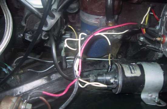
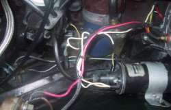 Here is a shot of my (not terribly neat) wiring. (Didnt have any 12 gauge Brown wire. Had to use Red. Later, I intend to remove the regulator altogether since I have never had a cover for it anyway.
I was surprised that when I plugged in the Field/Relay cable (energizing the alternator), the engine did not bog down at all (even though my battery was discharged down to about 11.8 volts just enough power to turn the starter). The alternator brought my battery up to full charge in about 5 minutes. With the engine running, the belt appears to run straight and true with no bouncing. I get about 14.4 volts at 700 RPM rising to 15.1 volts at 1500 RPM. The regulator holds it at that point at all RPMs above 1500. At idle with the headlights on the voltage drops to about 13.1.
This entire project only took a few hours, and not many dollars out of my pocket. I think the biggest downside is that, if the alternator needs to be replaced in the future, the mods will have to be done again. In retrospect, it occurred to me that I should have had them check the alternator before I purchased it. Had I got a bad one, Im sure my modifications would have made it unreturnable (and I suppose I can forget about the one-year warranty on this $30 part).
|