The MGA With An Attitude
DISASSEMBLING The SPEEDOMETER (#2) - ST-200A
This article was submitted by René Roelofs in the Netherlands
I've taken it all apart, cleaned everything with thinner, put a drop of sewing-machine-oil in the inner shaft, put is all together, placed it in the car.
I placed the needle on the white dot and turned it clockwise just more than 360 degrees thus letting it pass the 0-pin twice so a lot of pre-tension. Then nothing happened while driving; it kept standing on zero. Then I tried placing it on the white dot and only let it pass the 0-pin once, so very little pre-tension. Then while driving it waves plus-minus 30 mph and shows about 20 mph too much on average. Then I tried placing it on the 120 mph mark and letting it pass the 0-pin once, so average pre-tension. Then on average it showed the right speed, but the needle is still waving plus-minus 30 mph.
I disassembled it again searching for any item that wouldn't run smoothly. I cleaned the main shaft from the oil that I had put there earlier and put a tiny little bit of oil in the shafts of the read gears. It now runs even better.

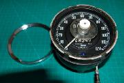
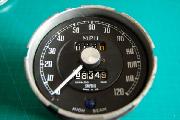
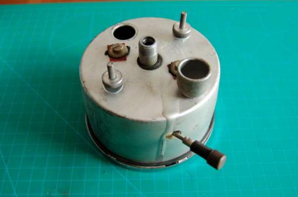
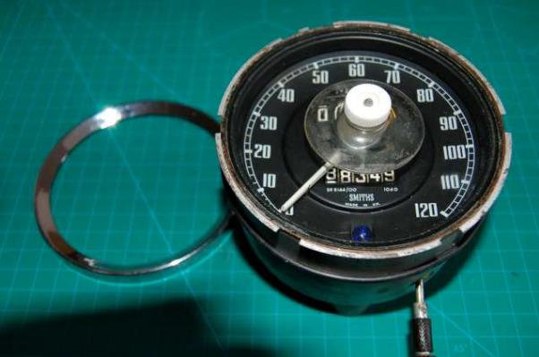
Casing on the outside. - The front of the casing, with the chrome ring taken of (a suction nap to take the glass off). - The front with the glass removed.
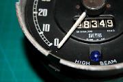
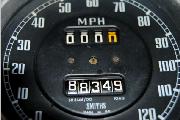
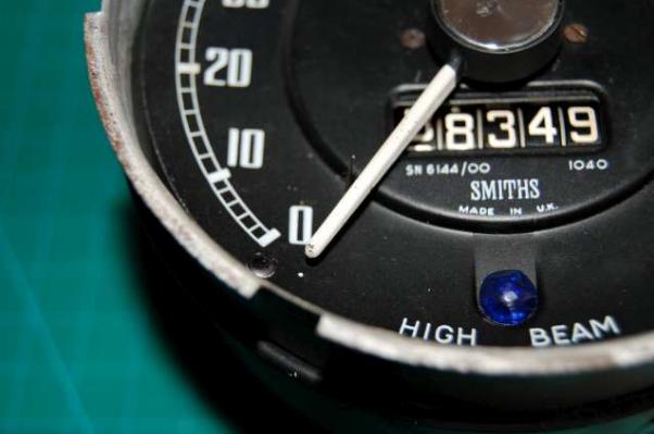
When I let the needle pass the 0-pin twice, it rests at the white dot. This is the completely unforced rest position. - The front with the needle removed. The faceplate is attached only with the two screws in the middle. - The face plate removed, Note the odo reset pin is still in place.
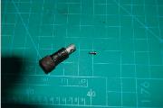
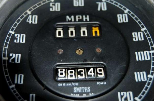
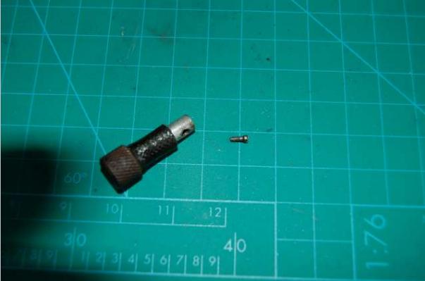
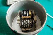
Details of for the odo reset pin. - The odo reset pin handle removed. (Note the squares on the green background are 1cm x 1cm). - The speedo can then be taken out of the case easy, by unscrewing the two screws in the back of the case. This picture shows the right order of items on the reset pin when the speedo is out of the case.
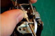
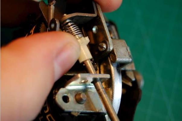
Another detail of the reset pin near the day-counter, Note the E-ring on top of the reset-pin. - There is a small pin in a hole in the reset-pin which disappears inside the white gear and can be seen right under my thumb thats lifting the gear up.
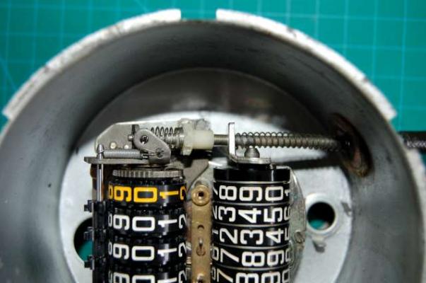
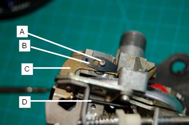
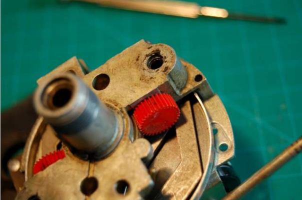
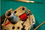
Details for the driving mechanism for the day-odo, the top side of the speedo.
A: Pin that is on top of the red-gear (not shown in this picture).
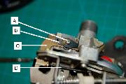 This pin is a-centric and rotates as the red-gear rotates.
B: Clip. This clip can be removed by pressing down and moving to the right in this picture. Before this can be done it needs to be lifted a little bit because right above the arrow-head it is locked in C.
C: a brass hammer driving the day-odo.
D: a very thin but about 1 inch long spring holding C in place. (both sides of the spring have a O-shape ending)
Once clip B is removed, then the pin A can be pushed down, and on the bottom the red gear comes loose and hammer C comes loose as well.
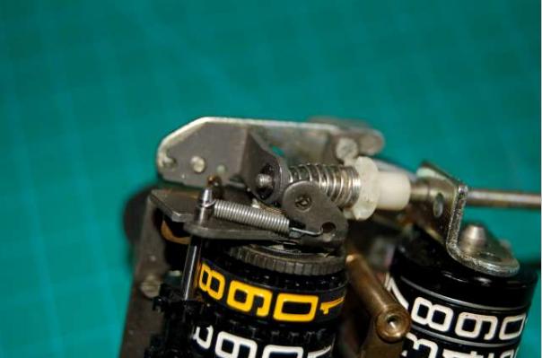
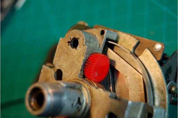
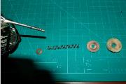
The red gear for the day-odo - On the bottom side is similar. But the hammer is much smaller and the spring has an O-shape ending on the speedo but a C-shaped ending on the hammer-side (the left side on this picture). - The red gear for the day-odo on the left, and the red gear for the total odo on the right. Note the reset pin is still in place on the bottom right.
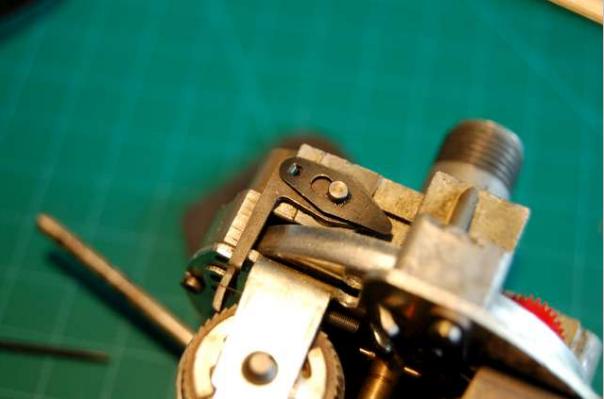
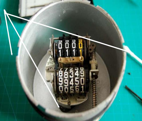
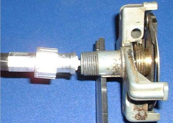
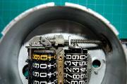
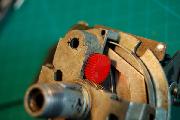
 Once taken the clips, the hammers and the red gears out, the entire odo can be taken out by just for small screws, as indicated by these white arrows the fourth is on be upper side. The removal of the springs must be done carefully, if they jump away its hard to find them back. You will need to remove the reset-pin before this. Remove the E-ring and gently take it out. In the very center of this picture you see the pin where the needle is on. When removing the odos this comes loose as well. The pin in on a spiral shape spring.

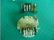
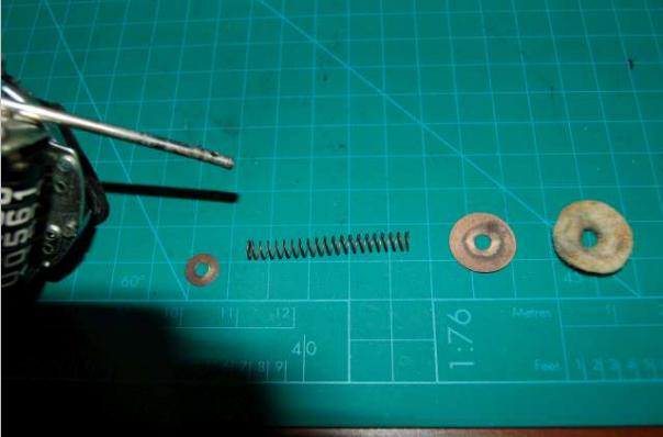
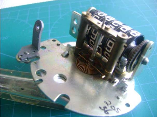
This is the odo with the speed spring in the center. - Here we have the day(upper)-odo and the lower odo removed from the body. - Once the spiral shape spring and odos are removed. you get this on the right side.
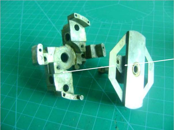
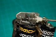
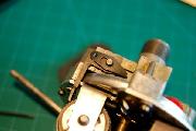
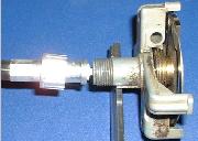
 And heres my picture of the same items. The arrow indicates one of the two spots where these who items are joined together. On the rightmost you see the rotating magnet that drives the needle.
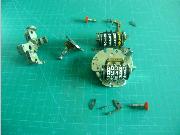
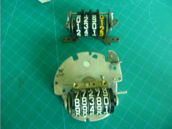
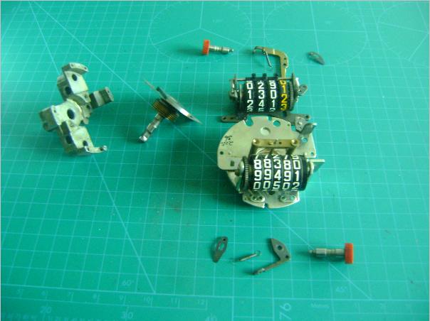
And then another picture the parts inside. On the top row, from left to right:
The red gear with axle and a-centric pin, the hammer-like brass that drives the day odo (or is it pendulum), with the spring still attached and the clip.
In the middle row, from left to right: The body the turning part, the day-odo and the odo with the centric-spring and needle drive.
On the bottom row, the clip, spring, hammer (pendulum) and red gear for the normal odo.
|