The MGA With An Attitude
POWER BOOSTER For MGA Brakes, #1 - BT-201A
At 01:18 AM 5/31/05 -0400, Jeff Becker wrote:
"I have enclosed the pictures of the brake booster. I will try to explain what I have done."
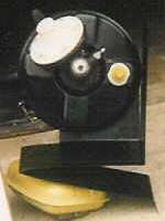
One picture shows the brake booster bracket out of the car. I did a dry fit of the unit drilling holes to mount it. I wanted a unit that would hide from site on the car and that would be easily removed in the future when it fails. [Not much on confidence but I like the service consideration.] That is why I use bulk head fittings. It makes it very easy to remove and replace quickly.
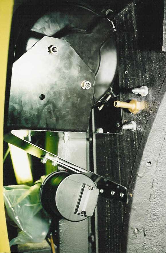
One of the pictures show the bracket mounted inside of the fender with the bulk head fittings in position but not hooked up yet. Under the brake booster bracket is the cruise control. I used a right angle drill to drill the holes to mount the bracket. I then used a rivet gun to lock in the bracket as it shows in the picture. (Click for larger pictures).

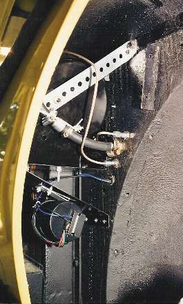
The next picture shows the unit completely hooked up. The unit seems to have had a little wobble for which a bracket was built to stabilize it. The top of the bracket goes to the fender bolt behind the splash apron. The other end of the bracket goes to the booster to lock it in position. The brake line from the master cylinder goes to the bulk head fitting behind and under the vent cowl [Hide the fittings here in the engine bay]. This line is picked up inside the fender to the brake booster. The other line to the brakes go from the brake booster to the inside of the fender bulk head fitting and is picked up in the engine compartment next to the other brake line. This line goes to the four way line at the frame to feed all the brakes.
The back of the intake manifold was drilled to fit a vacuum pick up fitting. I chose this because if in the future I wanted to reverse this, only a new end plug would be needed (like those used for a core plug). The local hot rod shop made a 5 inch S/S braided line to attach to a metal line that was clamped to the fire wall and fitted to the bulk head fitting next to the brake lines as shown in the pictures. The S/S vacuum line allows for engine movement.
The brake booster was bought from Victoria British and is a Armstrong. kit. This kit comes with all the needed parts to hooked it up. An in-line one way valve is supplied with the booster. The only thing that needs to be bought is the extra brake line and a brake flaring tool to custom fit the lines. The fittings are not easily detected including the vacuum line unless someone looks very hard. Once the splash apron is remounted, the brake booster is invisible.
All the fitting of this unit is done WITHOUT REMOVING the fender to install or remove the booster. I just remove 4 bolts which hold the booster to the mounting bracket, unhook two brake lines and the vacuum line at the bulkhead fittings, and out it will come in about 15 minutes. There is about 8-9 inches of clearance to the outside fender and this unit has about 1/2 inch of clearance on each side.
The vacuum [for the cruise control unit] comes off the same line as the brake booster with a extra vacuum tank for the cruise control. This unit was bought at a local auto parts store Kragens. I also have seen this unit in J.C. Whitney. It costs about $100. This is a very nice feature for driving on freeways or long drives as sometimes my feet/legs get cramps trying to hold it in a awkward position to give it gas. The line for hook up is connected to the passengers side throttle rod inside passenger seating area. I tried to make all changes so they could be removed without any damage to the car and OUT OF SIGHT of anyone so the modern equipment will not be seen.
Jeff Becker
After a little more chat this merits a few additional notes. The first picture at top shows the booster mounted on the bracket with nose to the front. The final installation has the booster mounted with nose to the rear. Apparently this is dictated by the space limitation behind the splash panel inside the MGA fender, where the narrow nose of the booster fits into the narrower space aft of the step in the foot well.
Notice the long run of hydraulic tubing in the last picture where it passes over the top of the booster. This still needs a P-clip with a rubber sleeve to secure it in mid run (about at the location of the upper bracket) to suppress shake and vibration in order to prevent stress fracture of the tube.
|