The MGA With An Attitude
MGAguru.com MGAguru.com
Fighting FOG LAMP BRACKETS -- BP-100

May 28, 2012 - This problem has been around for a long time. The following photos and notes come from Tony Clarke who has been diligently fettling with this for some time. The fog lamp brackets were purchased from Moss Motors, October 2004 (RH) and July 2007 (LH), so the problem has been around at least that long. We all likely know that the discussion of this issue has been making the rounds of the email lists and bbs for at least as many years. A recent message from Moss Motors USA states, "only one other person has complained of fitting problems in the last 5 years". If this is true, then a lot of the blame for continuing bad parts lies with the customers who don't bother to complain or return the bad parts. If we keep on buying this junk without complaining, they will keep on selling the same crappy parts.


1

2

3

Pix 1 – when first assembled with the top bolt (middle hole with loose nut & bolt for location purposes) the SL bracket front mid section would not push in flush with the Bumper bar.   Pix 2 – shows the slot actually touching the weld.   Pix 3 – shows the correct cap bolt (domed) touching the weld thereby pushing the bolt thread further along the slot as shown in Pix 4. This bolt goes into a slightly enlarged “top” hole through both B-bars preventing the SL bracket (SLB) mid front section from sitting tight up against the B-bar. The only fix I could think of was to file the B-bar’s top holes back further which cured the flush fit of the SLB mid front.


4

5

6

Pix 4 - To avoid the weld the adjustment is lost.   Next, and far more important, pix 5 – shows a 12mm bolt in the central hole for location purposes in order to mark and drill the bottom hole. Note top hole marked ready to elongate with file.   Pix 6 – shows top hole now filed to allow adjustment of SLB. Bottom hole is now drilled 1/64” (16thou) oversize to take the 5/16” bolt.


7

8

9

Pix 7 – 12mm locating bolt removed, top and bottom SLB bolts fixed – all looking good at this stage with SLB mid front section now against the B-bar.   Pix 8 – Bumper springs attached, SLB arm pushed in as hard as possible to reduce contact between SLB arm and the overrider – holding thus whilst tightening top SLB bolt (I found that tightening the lower one first certainly pulled the SLB arm out towards the overrider).   Pix 9 – Overrider securing bolt ready to go – central in the hole.


10

11

12

Pix 10 – Tightened overrider by hand until no discernible play evident. This side away from the SLB arm sits well against the B-bar.   Pix 11 – The SLB arm side of the overrider is nowhere near the B-bar and further tightening with spanner does not bring it in any closer at all. It is pointless trying the plastic channeling!   Pix 12 – Just to illustrate, the gap is 9mm.

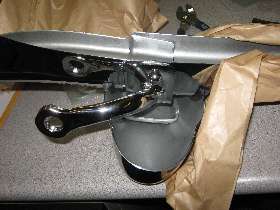
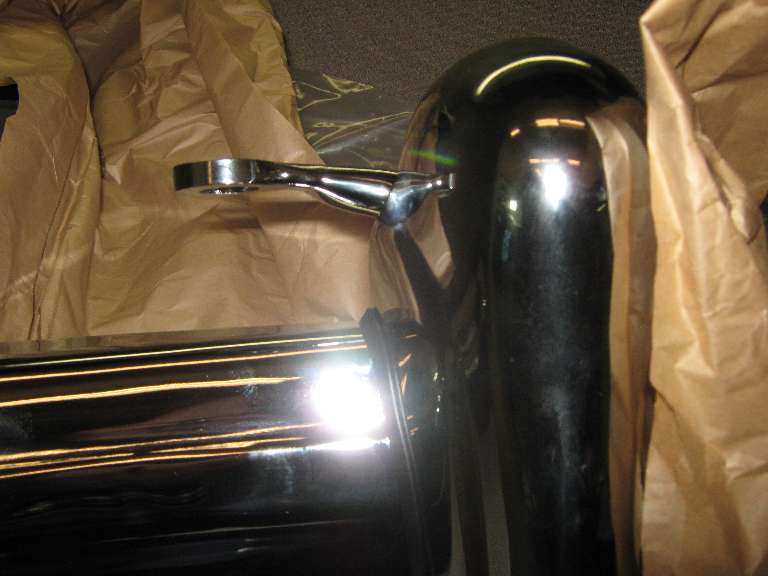
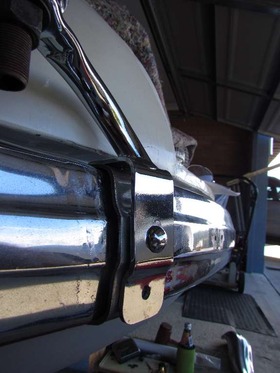
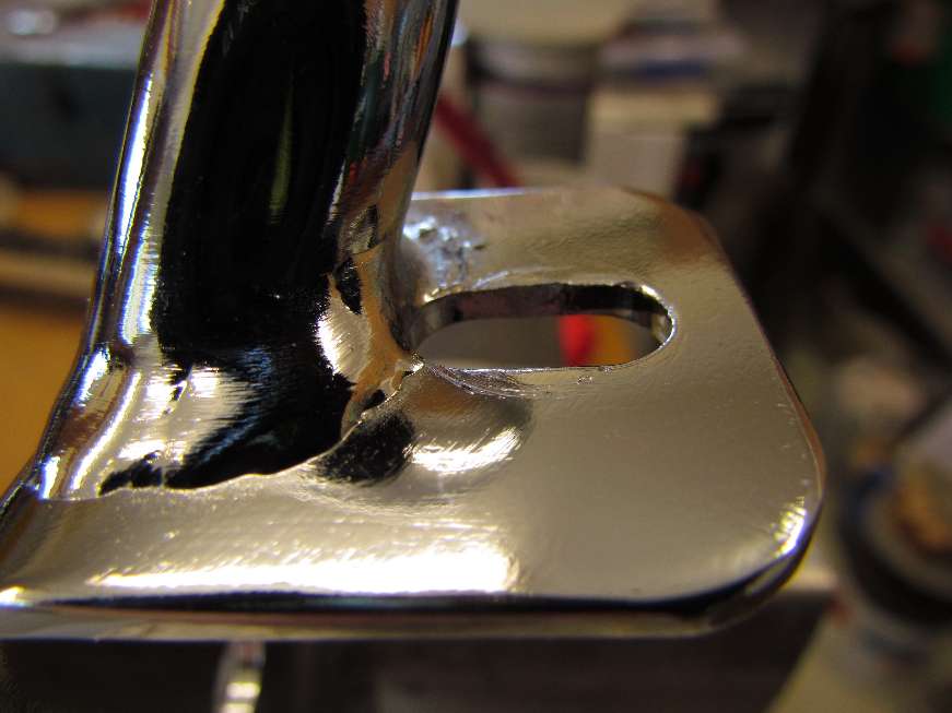
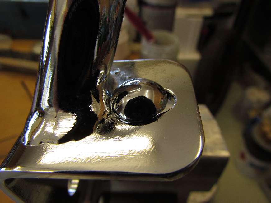
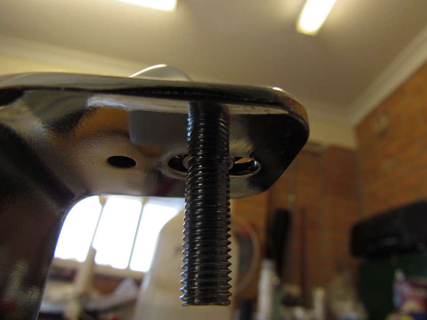
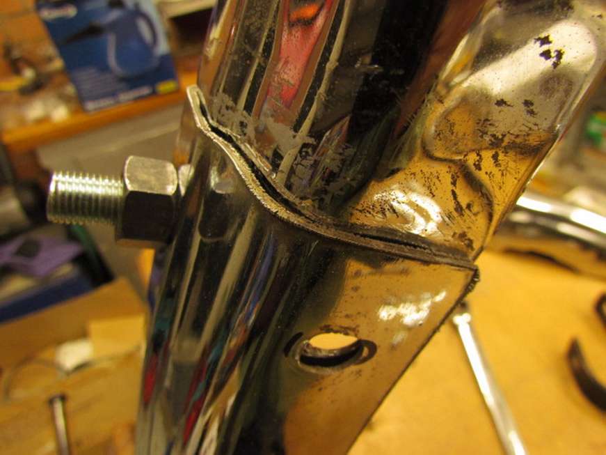
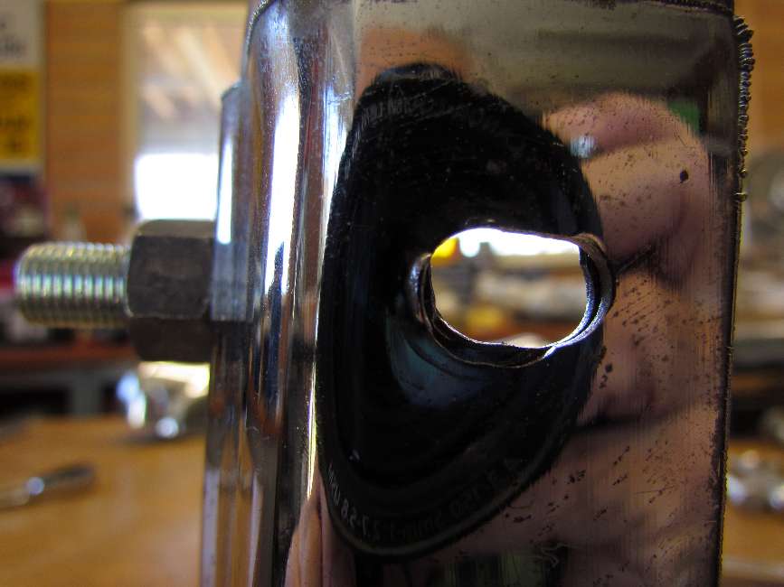
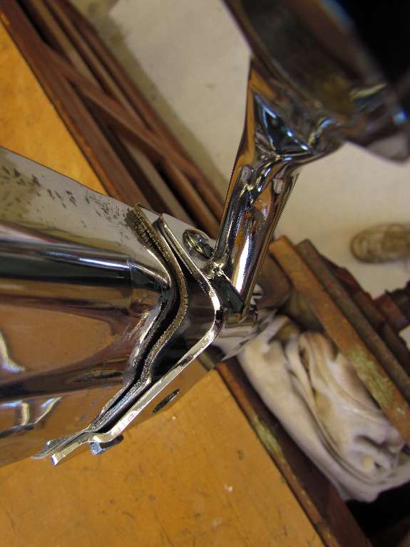
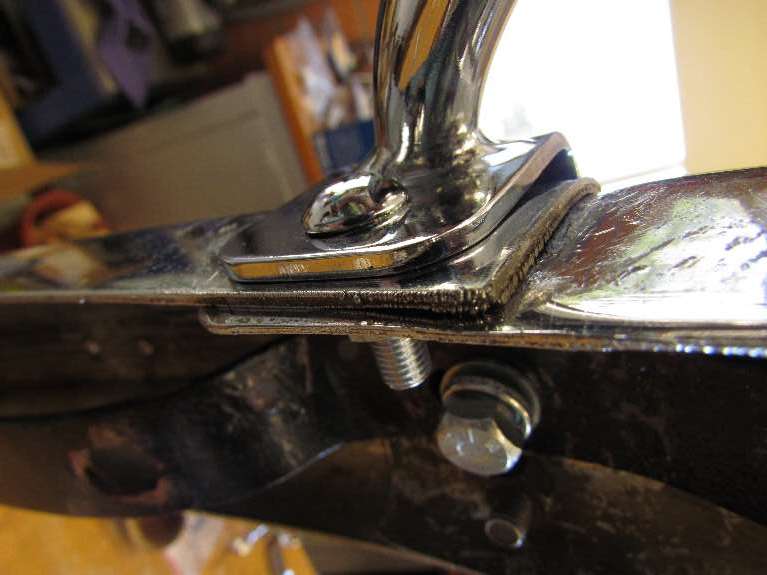
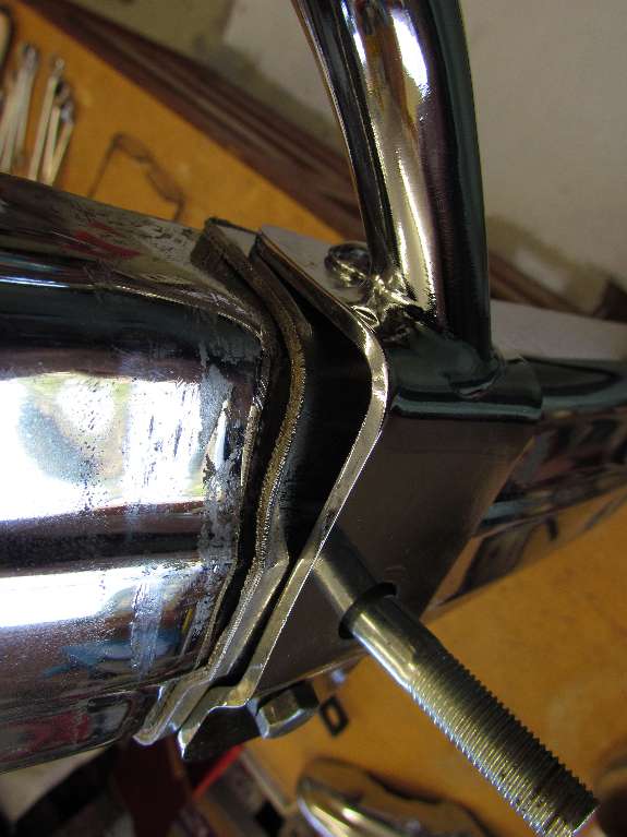
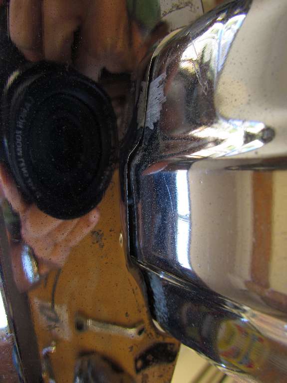
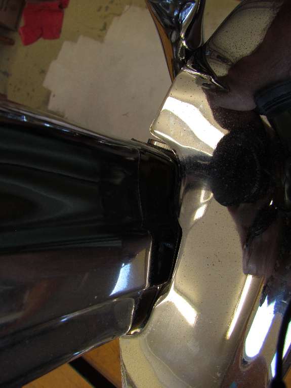
By this time Tony has had to grind some chrome off of just about every part he has touched, and it looks like he is about to grind a 1/2-inch notch in the overrider to clear the bracket and allow the overrider to seat properly against the bumper. Stay tuned for more notes to come.


13
June 7, 2012 -
More progress.


14

15

Pix 13 – I marked the point I felt was the optimum point to heat and bend the bracket arm also marking each side to illustrate not to bend outside those points. Initially I heated/pushed the bracket arm back in small stages to fit and test the overrider for obstruction, finally getting an acceptable position where the bracket arm still touched the overrider but only with minimal pressure.   Pix 14 – I found the left bracket had to be bent a further 16mm away from the overrider, measured at the lamp mounting hole as compared with the right, untouched Moss bracket.   Pix 15 – The second bracket was far easier, knowing how far to bend. This time I decided to try for a small gap and had to push the bracket 19-mm further than the original Moss one giving me a gap of less than 5 thou. From the surface of the Bbar to the top of the bracket arm lamp mounting hole is 50-mm but I feel that about 3-mm higher would have the advantages of more space behind the lamp as it will be higher up the divergent curve of the bodywork as well as the overrider which may help with clearance. Anyone with an original bracket could check and verify if their overrider and lamp bracket has a gap and if the bracket height is as mentioned above. Feedback helps a great deal; contact Barney please!


16

17
 

Pix 16 – A full bolt up showing 15-mm gap between lamp and bodywork. Here I need help from anyone who has an original set up on their “MGA” and can advise if the gap is similar. Note the overrider PVC moulding are inserted now.  . Pix 17 – The front view as fitted. More help comparing needed here from original setup MGA owners to say if this position is the same as theirs. I thought it could have been a little to the right thereby obviating any obstruction of the headlamp.

NOTE – the 15-mm gap mentioned in pix 16 can vary depending upon how far the set of the springs behind hold the bumper bar away from the front valance. If undertaking heat bending I would recommend that a little each time, test and increase is the route to take.
I also noted that the front centre profile and the top surface of original bumpers is 90Ί yet the Moss brackets are a larger angle and the Scarborough Faire bumper bars are curved on the front centre profile and are not 90Ί either.
Feedback will let me know whether I have got it right or need to fine tune - so email feedback to Guru Barney please.

These photos also have been sent to Moss Motors, and time to wait for their response. Meanwhile I can only recommend not buying this part from them until there is a satisfactory resolution to this problem. Unless of course you are willing to spend the time to modify the part to fit and have it re-chromed.

See additional comments in the Faulty Replacement Parts Report FT-051.

HomeBackTopNext
Thank you for your comments -- Send e-mail to <Barney Gaylord>
© 2012 Barney Gaylord -- Copyright and reprint information