The MGA With An Attitude
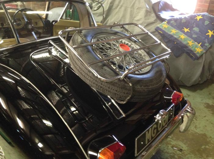
TIRE CARRIER Addition To Standard Luggage Rack - AT-102M
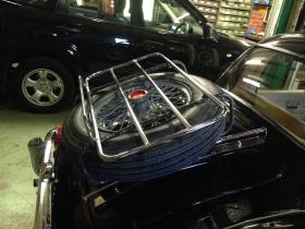
This design is from Colin Cleaver in Western Australia. Before you ask, you do have to remove (unbolt) the top rack to get the tire in or out.
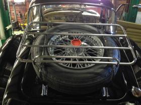
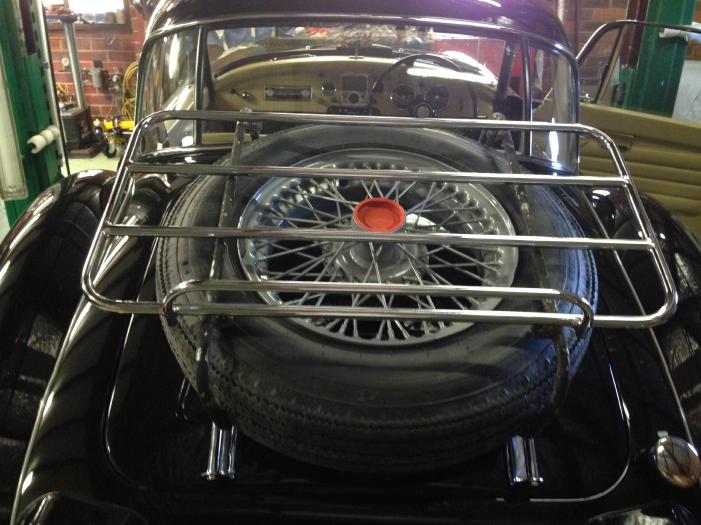
The brackets shown were originally used with the Twin Cam wheels, but wire wheels fit as well. On the new drawing the vertical offset is to minimize any stress at the connection points. The existing light gauge MS set (shown) has done many trouble free miles, but is showing some small hairline cracks in the tubing at the lower connection to the boot rails. The small offset should reduce stress at this point, with perhaps a thin rubber washer.
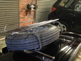
The only extra fixings that are required are (4) 5/16-24UNFx7/8" long bolts (316-SS) with nuts and spring washers to fit the new brackets to the existing rails. The existing (4) rail to rack bolts are reused.
There is a lot of extra weight on the existing (flimsy) MGA Hinges when opening and closing, but my experience has been that over various 3 or 4 week tours, with sympathetic use, no damage to boot lid or hinges occurred. Perhaps reinforced hinges would be the next step, but where do you stop?
Have got a price from my local SS fabricator of $270-AU for 1 Set or $250-AU each for 3 or more sets in polished Marine Grade 316 SS.
Barney's comments:
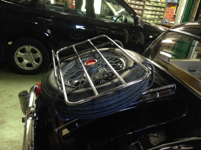
To R&R the tire, in theory you could just remove the added loop from one side (4 screws). But that would leave the top rack secured with only one loop on the other side, which would be fragile and likely to break something. Otherwise remove the top rack (4 screws) and the loop from one side (2 more screws).
There may be an easier way. Remove only two screws, one top and one bottom at one corner, like right side at the rear. Loosen the two screws at front of the same loop. Swing the rear end of the loop out sideways to free the tire while leaving the top rack supported on three points.
There is a mechanical flaw in the design. If you push sideways on the top rack it will put very high loading on all 8 screws holding the loops. If the assembly jiggles a bit sideways while driving it will do the same. A repetitive jiggle will lead to fatigue cracks (which were previously mentioned). The assembly needs an angle brace from top left to bottom right to prevent the sideways motion and high stresses on the fastening points.
If I was to build something similar, I think I would add a hinge at front (2 P-clips around a tube) and a couple of wing bolts at back. Then you could loosen the wing bolts and hinge up the top rack to install/remove the tire. Food for thought.
|